

Kawasaki Control Cabinet 1TR Power Program Board 50999-2924R02 Repair


1TR power program board functions:
1. Connect external safety circuits;
2. Detecting the status of safety circuits;
3. Check if the fuse of the safety circuit (F1) is blown;
4. Monitor the internal temperature of the controller and detect errors when the temperature is high;
5. Check if the safety circuit is functioning properly and notify the main CPU board 50999-0137 board;
6. Notify the main power supply abnormality from AVR to the main CPU board 50999-0137, and monitor the DC power generated by AVR;
7. When abnormal external power and DC power are detected, turn off the output of the AVR power supply;
8. Set the number of safety circuits (standard is dual circuits). At the same time, corresponding changes need to be made to the jumper wires of the MC power supply unit;
9. Set the time to turn off the motor power (hardware backup) after changing the "HOLD/RUN" (option switch) to "HOLD";
10. Notify the main CPU board 50999-0137 of the switch input status of the option operation panel. Additionally, turn on the indicator lights on the option operation panel;
11. Can install two quick option daughter boards;
12. Equipped with a switch that renders the limit switch function ineffective.
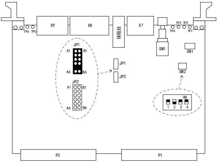
Switch function and settings
SW1 (switch that renders the limit switch function invalid): When this button is held down and not released, the limit switch function becomes invalid;
SW2-1: Set the number of safety circuits. (ON: single circuit, OFF: dual circuit);
SW2-2: Set HOLD backup time (ON: 2 seconds, OFF: not set);
SW2-3: Not used;
SW2-4: Not used.
X7: External emergency stop input;
X8: Safety fence, external grip triggering input, teaching status output;
X9: External controller power on, external motor on, external pause input, IO 24V output;
P1: System bus;
P2: Safety circuit input/output for emergency stop, teaching/reproduction, etc;
CN2: Connector for 12V power supply (optional);
CN3, CN4: connectors for option boards;
CN10: Mitsubishi SSC-NET emergency stop output.
Jumping feet CN1: used for debugging;
Jumper JP1: Emergency stop of monitoring operation panel/teaching pendant;
Jumper JP2: Do not monitor the emergency stop of the operation panel/teaching pendant.
LED display
LD1 (OPEMG): The "emergency stop" working status of the operation panel (normally: off, emergency stop: on);
LD2 (TPMEG): The "emergency stop" working state of the teaching pendant (normally: off, emergency stop: on);
LD3 (EXEMG): External "emergency stop" working state (normally: off, emergency stop: on);
LD4 (PSERR): Power program error occurred (normally: off, error: on);
LD5 (WDERR): Bus access watchdog error occurred (normally: off, error: on);
LD6 (+3.3V): Supply+3.3V power (normally powered on: on);
LD7 (+5V): Supply+5V power (normally powered on: on);
LD8 (+12V): Supply+12V power supply (normally powered on: on);
LD9 (+24V): Supply+24V power (normally powered on: on);
LD10 (ACCESS): Accessing the system bus (normally: lit).


